Friday, March 28, 2014

ARM T3 - Tic Tac Toe Playing Robot Arm


ARM T3 - Tic Tac Toe Playing Robotic Arm

I am going to tell you the story of our robot ARM T3, a robot capable of playing tic tac toe with a human. Here is the video of ARM T3 in action.


This robot has two main parts, vision system to detect board and mechanical arm to draw crosses on board. 

Mechanical Components


For implement robot arm we use low cost hobby servos and servo brackets. We bought servos from pololu.And servo brackets from ebay. Then we assembled brackets and servos and build 3 link arm and used a one servo for control of pen. It was not a hard task to this part.

And then we did some modeling of robot arm in Matlab so that we can do calculations easily. Here is a image of planning robot in Matlab.This image shows all accessible points to robot arm when it is placed at origin.

Eye of the Robot


And most important part of this robot is its vision system, we used a Logitech C270 webcam  to grab images of the tic tac toe board. Images grabbing and processing algorithm is implemented in a java program which runs on a laptop computer. This program uses javacv(openCV wrappers for java) for doing these image processing works. 
Before starting a game we calibrate the robot, in this stage our algorithm detects lines in the board and it identify positions of 9 squares. And it also programmed to identify circles drawn by human opponent on the game board.

How Robot thinks 


Also thinking where to play is also an important task. After identifying game status via image processing algorithm robot has to play on a suitable position. We use min-max algorithm for this tic tac toe robot to calculate best option to play. This min-max algorithm is also programmed in the previously mentioned java program. 

Interconnecting All things


Now I am going to tell you how these things are interconnected. 
As already mentioned robot continuously looks at game board to detect circles drawn by human.
As soon as it detects humans play, it updates the game status and calculate best option to play by using the min-max algorithm.
And then laptop computer which runs those algorithm sends necessary motor rotating angles to arduino board which then controls the servo positions.

This is how we came across with this little tic tac toe playing robot and we are going to develop it by using dynamixel servos so that maximizing its drawing capabilities.

Your suggestions are warmly welcome ! 

Tuesday, February 26, 2013

                  IR Sensor Panel For A Line Following Robot.


                       Most of the time we use IR(infra red) to detect the line which the robot should follow.There are some IR sensors with IR LED in a single package specially made for robotics.They normally costs around Rs.50.And we can easily make a sensor panel using those modules.


       There are two types of sensors in those packages.
                     
                       1.Resistor type
                       2.Transistor type

                      In the resistor type, the sensor works as a resistor.It changes the resistance through the sensor with the color.So,we can detect the line using that fact.But the voltage through the sensor changes by a very small amount with the color.And that difference is not enough to take as an input to a PIC.Because it needs at least 3.3v to identified by the PIC as an input.So as a solution we use a set of op-amps to amplify that small voltage difference.LM324 is an IC which contains 4 op-amps in it.we can use that one or any other op-amp IC to this circuit.below is the circuit diagram for a single sensor.But in the diagram the sensor is shown as a Diode.

         we can use 8 or more number of sensors as we wish.Because more sensors is better to build a very sensitive sensor panel.We can change sensitivity by changing the value of the 20k variable resistor.And can see if the input pin of the PIC is ON or OFF from the LED1.

                    In the Transistor type the sensor is a photo transistor.It acts as a normal transistor without a base pin.The current through the collector-emitter junction changes with the color.


          we can use an op-amp circuit for these sensors also.But these transistors give a large voltage difference for colors like Black and White.So,if we don't like to use a op-amp circuit, we can use the emitter out directly as an input to the PIC.Here is the circuit,
       You can use any type of sensors as you wish.But remember the more sensors is better for a very sensitive sensor panel.Normally we use about 8 or 10 sensors for a panel.But this can be changed with the task to complete.

       This is a ready made sensor panel you can buy.But it is more valuable if you make it by yourself.

Thursday, February 21, 2013

Drive Your Robot


Drive Your Robot


You can build a  simple mobile robot using two DC motors and two wheels. And now I am going to explain you how you can drive your robot. The driving mechanism now I am going to explain is differential drive.
The differential drive design has two DC motors in left and right which are attached  to two wheels. And since we need three ground contacts we need extra castor wheel.
Here by changing the speeds of the two motors we can make robot to go on different paths.


Differential Drive


So using differential drive we can achieve movements as follows
         Driving straight forward : VLeft = VRight
         Driving a right curve :        VLeft > VRight
        Spot turning : Vleft = -VRight
So by adjusting the speeds of two motors we can move the robot as we need. So to control the motor speeds we need a motor controller circuit. If you don't know about motor controller you can view the article about the motor controller in this blog.         DC Motor Control Circuit For Your Robot

So we can change the motor speed by changing the given voltage to it, otherwise we can change the voltage given at enable pin of the motor controller to change the speed.  

 This could be achieved by using the PWM output pins in your micro controller. So let's see what is Pulse Width Modulation

Pulse Width Modulation
           
            In order to control the motor speed we can generate a voltage signal that is proportional to the motor speed. In other words we can generate an analog voltage signal to control the speed. But instead of generating analog signals we can use pulses of digital signal to achieve this. By changing the width of pulse we can generate the analog voltage signal to control the motor. This method is known as Pulse width modulation. And in most microcontrollers there are PWM output pins to control DC motors, or drive servo motors etc.

Pulse Width Modulation


So by changing the voltage at enable pin of the motor controller we can drive our robot.
So next our target is to drive the robot according to its environment, for example following an line, or avoiding obstacles etc. So in my next post I will explain how to control the robot motion according to its environment.   There I will discuss about the PID control theory to move robot.

Wednesday, January 9, 2013

Build A Motor Control Circuit For Your Robot


DC Motor Control Circuit for Line Following Robot


If you are going to build a little line following robot robot, definitely you are going to need this. I’ll explain why …

If you are willing to use any micro-controller for controlling, it can’t provide sufficient current for a dc gear motor. As an example pic16f877A microcontroller can only supply up to maximum 40 uA from an output. This current is not enough for a gear motor. Micro-controller can only give the control signal.

Now we need to find another way to supply enough current to the motor. The solution is H-Bridge.


THE H-BRIDGE


A very simple H-bridge is shown in figure. S1 to S4 are switches and M is the Motor. Vs+ is the required voltage supply for the motor. By turning ON S1 and S4 we can rotate the motor clockwise. Similarly, turning ON S3 and S2 we can rotate the motor anti-clockwise. By turning ON all switches we can stop the motor!..


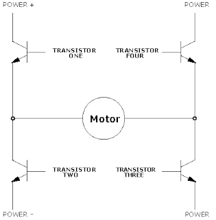
Actual H-bridge has 4 power transistors as switches. Then we have to bias each transistor same as switches. That could be easily done by the control signal of our microcontroller.


Fortunately we don’t have to make this one by our own. L298 is a very popular high voltage, high current dual full-bridge driver designed to accept standard TTL logic levels and drive inductive loads such as relays, solenoids, DC and stepping motors. You can use one L298 IC to control 2 dc motors up
to 2A for each.

To control motor speed PWM (pulse width modulation) method should be used.


Download L 298 Data Sheet


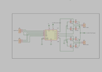
Motor Controller Circuit for 2 DC motors


Figure 1 L298 Motor Controller


Motor1 input and Motor2 input are consist of three input signals. IN1, IN2 for the motor1 and IN3, IN4 for the motor 2. ENA and ENB are the enable signals for the motor1 and motor2 respectively. An example input method is given below.


High = Logic High (in most cases, 5V)


Low = Logic Low (in most cases, 0V)


X = High or Low (whatever)


ENA/ENB
IN1/IN3
IN2/IN4
Function
High
High
Low
Forward
High
Low
High
Reverse
High
High
High
Fast Motor     Stop


Low
X
X
Free Running


Pin 15 and Pin 1 are labeled as Current Sensing A and Current Sensing B. These pins can be used as a feedback to the main control system as an indicator about current of the load (Motor). If it is above the maximum level, we can quickly disable the motor.


  • Remarks

As previously mentioned L298 package has 2 H-Bridges. If we want more current for our DC motor, we can couple these 2 H-bridges in to one bridge. This implementation can provide up to 4A for a single motor.
. 


Above diagram shows how to do it.


An external bridge of diodes is required when inductive loads such as dc motors are driven: Shottky diodes would be preferred.


Shottky diodes are quick responsive diodes. Switching from forward bias mode to reverse bias mode takes less than 100 Pico seconds. Normal diodes take roughly 100 ns.


To safeguard the H-bridge from Electromagnetic Forces of a motor (when a rotating dc motor stops quickly, EMF is generated. This EMF can damage H-Bridge) 4 shottky diodes should be used.


1N 5818 and 1N 5819 are two examples for shortly diodes.


Making of this motor controller on a vero board is not a complex task. So make one of these for your little robot right away!!