DC Motor Control Circuit for Line Following Robot
If you are going to build a little line following robot robot, definitely you are going to need this. I’ll explain why …
If you are willing to use any micro-controller for controlling, it can’t provide sufficient current for a dc gear motor. As an example pic16f877A microcontroller can only supply up to maximum 40 uA from an output. This current is not enough for a gear motor. Micro-controller can only give the control signal.
Now we need to find another way to supply enough current to the motor. The solution is H-Bridge.
THE H-BRIDGE

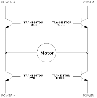
A very simple H-bridge is shown in figure. S1 to S4 are switches and M is the Motor. Vs+ is the required voltage supply for the motor. By turning ON S1 and S4 we can rotate the motor clockwise. Similarly, turning ON S3 and S2 we can rotate the motor anti-clockwise. By turning ON all switches we can stop the motor!..
Actual H-bridge has 4 power transistors as switches. Then we have to bias each transistor same as switches. That could be easily done by the control signal of our microcontroller.
 |
Fortunately we don’t have to make this one by our own. L298 is a very popular high voltage, high current dual full-bridge driver designed to accept standard TTL logic levels and drive inductive loads such as relays, solenoids, DC and stepping motors. You can use one L298 IC to control 2 dc motors up
Download L 298 Data Sheet
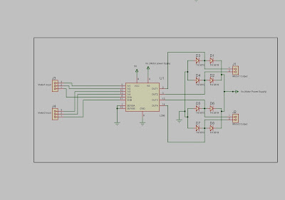
Motor Controller Circuit for 2 DC motors
Motor1 input and Motor2 input are consist of three input signals. IN1, IN2 for the motor1 and IN3, IN4 for the motor 2. ENA and ENB are the enable signals for the motor1 and motor2 respectively. An example input method is given below.
High = Logic High (in most cases, 5V)
Low = Logic Low (in most cases, 0V)
X = High or Low (whatever)
ENA/ENB
|
IN1/IN3
|
IN2/IN4
|
Function
|
High
|
High
|
Low
|
Forward
|
High
|
Low
|
High
|
Reverse
|
High
|
High
|
High
|
Fast Motor Stop
|
Low
|
X
|
X
|
Free Running
|
Pin 15 and Pin 1 are labeled as Current Sensing A and Current Sensing B. These pins can be used as a feedback to the main control system as an indicator about current of the load (Motor). If it is above the maximum level, we can quickly disable the motor.
- Remarks
As previously mentioned L298 package has 2 H-Bridges. If we want more current for our DC motor, we can couple these 2 H-bridges in to one bridge. This implementation can provide up to 4A for a single motor.
Above diagram shows how to do it.
An external bridge of diodes is required when inductive loads such as dc motors are driven: Shottky diodes would be preferred.
Shottky diodes are quick responsive diodes. Switching from forward bias mode to reverse bias mode takes less than 100 Pico seconds. Normal diodes take roughly 100 ns.
To safeguard the H-bridge from Electromagnetic Forces of a motor (when a rotating dc motor stops quickly, EMF is generated. This EMF can damage H-Bridge) 4 shottky diodes should be used.
1N 5818 and 1N 5819 are two examples for shortly diodes.
Making of this motor controller on a vero board is not a complex task. So make one of these for your little robot right away!!


No comments:
Post a Comment